Showing posts with label CAM. Show all posts

Sunday, October 6, 2019

An Engineer's Spoon

This project came about from a need for a kitchen spoon. Now you would think you could just buy one of those, but where is the fun in that? The bowl is machined 304 stainless steel, with an Osage Orange handle. I was inspired by a limited edition Le Creuset cast iron skillet I came across a few years ago. It was ridiculously expensive, but had a nice aesthetic where the wooden handle blended smoothly with the metal body. Around a year ago I needed a nice kitchen spoon. Growing up with wooden spoons, I gravitated towards that as a choice, but there weren't really any I liked and over time the wood really wears because its never hard enough.


The alternative is stainless but the handles on those aren't comfortable. Remembering the aesthetic of the skillet I liked, I designed a spoon. That spoon was never made. I designed it more as an experiment and didn't really think about how I use spoons when cooking and what manufacturing methods I have available to me. I shelved it and forgot about it for a bit. 


Earlier this year, we finally got our Okuma 5-axis up and running (same machine in the impeller post) and after a busy semester learning a new machine, control, writing a post processor, and making parts (more on those parts to come), I had time on the machine to make a spoon. I dusted off the old CAD model and made a bunch of changes. The bowl was slimmed down to fit the stock I had, the leading edge was thinned out to make scraping the bottom of pots easier, and some of the lines and tangencies were refined. I did all the modeling and programming in Fusion360, and since the first spoon design, they added some more features that helped me refine the look. 


Programming this was a good learning experience for 5 axis work. Stability was a big issue throughout as well as tool access. Off the machine I was quite happy with the finishes. This is due to the superior quality of Okuma, as well as having some really top notch Sandvik tooling. After machining, I just sawed the part off the remaining stock. At this point an interesting issue was presented to me; how do I drill the hole for the handle when there are no reference surfaces, flat or parallel edges or really any way to hold this part? I created an aluminum tool that was machined to be a perfect negative of the bowl. This gave me support over a large area, as well as rotational alignment to clamp it in tall jaws seen below. From there it was easy to indicate the round shank of the spoon and drill the hole. Last was the handle, which I completed over the summer. Very straightforward compared to the bowl. Osage Orange was used because it is very hard, strong, and moisture resistant. Ideal for use in a kitchen without the need for any finishing. Also it matches a kitchen knife handle I made a few years ago.


Having used this spoon for a few months now, I do have some lessons learned. First, weight distribution. The spoon has a heavy metal bowl and a very thin, wooden handle. Its front heavy. If I had thought of this, I could have checked center of gravity in CAD. Spoon still works fine but it takes some getting used to the unique weight distribution. Second, Loctite 380, my favorite adhesive, is not good at bonding to wood in high humidity environments. The joint has come loose over time, but the machined fit is so tight, that once the handle heats up at all in a pot, it swells enough that it won't come off; so no long term issues. Last, I would use a harder material next time. Maybe a 17-4 PH. Something that resists tapping on the edge of a skillet a bit better. 

Now all I need is a fork.....


Sunday, June 9, 2019

Liquid Oxidizer Impeller

At my school there is a model rocket group, Launch Initiative. They design, build and fly mid size model rockets. Typically they use purchased solid rocket motors, or hybrid (solid fuel, liquid oxidizer) motors they design and build. While working on some other projects, they are planning for the future and trying to push their engineering skills by designing a hybrid rocket motor with a oxidizer turbo pump.

This project was more of an experiment and test of skills, and this version wasn't intended to fly. Twofold to this project was the design and mathematical modeling of a pump impeller and turbine, and second to manufacture the pumps and impellers. The design was done by one of the Launch Initiative team members; I was only on board for the machining.


This is the second generation of pump impeller, made in aluminum. This machined one is scaled down from its original size to result in a roughly 4 inch (100mm) diameter. This scaling was done primarily for cost; I already had material for this smaller size. It was also done to replicate the size of what a final impeller would be. A flight ready version of this impeller would be out of stainless, and the turbine would be inconel. When I finished machining this impeller, the team had already progressed to the fourth generation of impeller which added splitter fins. 

All programming was done in Fusion360 with a custom post and run on an Okuma Genos M460V-5AX. Absolutely fantastic machine, no complaints with it. There is a real joy in using a machine that does what you tell it to first time, every time. I cannot say the same about Fusion for this type of work; not at all suited to it. I first tried to program the part with simultaneous 5 axis moves, but Fusion couldn't handle it. In the end I had to split all the faces up and do them as positional 5 axis moves. Visually not as good but these impellers would have to be polished before service anyway so this would be functional.

Cycle time on this was around 4 hours a part. This could definitely be cut down by pushing roughing and semi-finishing federates. Using a better CAM package to optimize the tool paths would also help. I have an Esprit license which is the preferred CAM for Okuma machines (they have a partnership and sponsor my school), and the machine simulation models are very accurate. 

Checking clearance inside the machine when testing
Fusion doesn't have machine simulation, so I was a little weary for some of the 5 axis moves. I had improvised a basic simulation that would prevent major crashes, but it was inaccurate for close clearances. There was a risk of crashing the back of the spindle into the table when rotated up at steep angles. This was solved by propping my camera on the trunnion inside the machine. From there I could stream to my smart phone and zoom and watch the clearance in critical areas. I would run the part dry with no stock at a slow speed to I had a hope of being able to react if something goes wrong.

The machining process was quite straightforward. Most of the tooling was Sandvik inserted, solid and drills. I used to be skeptical of the premium price of Sandvik solid carbide tooling. After using them for an extended period of time, I think they are worth the price. The carbide quality is just phenomenal and the cutters just last and last and last. Maybe if were paying for all the cutters out of pocket, I would change my tune but as long as work is buying them (or Sandvik is donating them).

Various stages of machining

In the end, this part was also used as a demo piece for an on-campus creativity festival. I put together a little display with the different stages of of machining seen above, along with the tools used and the chips they produce. This was to show to people who don't know about machining how a part is made. A lot of people thought these impellers were 3D printed and were surprised to find it was cut out of solid.

The project was fun. I think I made 6 of these in the end. I would like to revisit it eventually with a better CAM package. This was only my second 5 axis project and I made it with only 100h of 5 axis machine time under my belt.

Pretty reflections after roughing

Saturday, June 9, 2018

One Day Build: Strong Indicator Arm

For a while now I have been using one of these ubiquitous Swiss made indicator arms. It works okay but I've never been fully happy with it. They have too many joints and too much wiggle for precision work. Even on the best units I have seen problems with the indicator alignment when indicating small holes. The dovetail isn't perfectly radial with the stem and it side loads the contact point.


I wanted a better, simpler solution. I came up with this single pivot arm inspired by some cheap indicator arms I've seen. The clamp plates are hardened A2 and the shank is 60 case Thomson rod. The spherical surface on the clamp plates were surfaced on a CNC and match the spherical indents on the shank.


The screw is kinda cool. Its a standard SCHS with a little plastic knurled knob pressed on. I didn't know these existed until one of the toolmakers I work with bought some a job. The clamp gives just enough friction on the joint that it wont be knocked out of place, but can easily be adjusted by hand.


The little spring on the front of the clamp is just there to hold the clamp plates on the shank and the dovetail open when the indicator is not on the arm. Right from the start the radial alignment wasn't perfect. This this design, that alignment is easily adjusted by grinding the faces of the clamp plates to affect the angle the indicator is held at. With a bit of fiddling I got the contact tip to less than 0.25mm radial misalignment. 

This isn't a perfect solution for every application but it works perfect for any time you need an indicator in a mill spindle. Going forward I would make a second one of these with a 10mm reduced shank for using in my small drill chuck.

Example of the suspect indicator arm. Photo from wttool.com

Tuesday, May 8, 2018

One Day Build: Gale Crater Topographic Model


This project was inspired by a kick starter project I found where backers were funding large scale models of the moon (500 mm dia.). The models (which were castings of a high quality 3D print) looked stunning, especially when lit. Poking around out of curiosity, I found NASA has a substantial collection of 3D resources available here including 3D models of spacecraft, satellites, asteroids, comets, and Lunar and Martian surfaces.

I decided to carve a small model of Gale Crater, the current location of the Mars Science Laboratory. The model from NASA had a 3x vertical exaggeration, which I reduced to 2x. Made out of a scrap of PVC, the model is around 200x150 mm. It ran on a machining center overnight and took an estimated 16 hours. It was supposed to run faster, but motors on this machine are very low torque, so the feed rate is dynamically throttled to ensure the axes won't overshoot. All mesh editing and programming I did in Fusion360 and it ran on a Trak 2 Op.


As a result of mesh reducing, the model has a beautiful, faceted effect


Monday, April 30, 2018

Modular 18650 Battery V3

This is another post in the series about designing an electric moped. This post mainly details the system architecture and high level design. I avoid delving into the calculations I used. This post also doesn't cover BMS design and programming. This may be detailed in a future post.

For designing the battery I focused on the maximum power draw required. For my intended use - running around town while at school - I'm not particularly focused on range. While I aim for a 100km range, I don't have enough information about my preliminary designs to know if this is possible. I began by calculating maximum power required. The motor will draw maximum power when accelerating so I decided on required power from my desired acceleration.

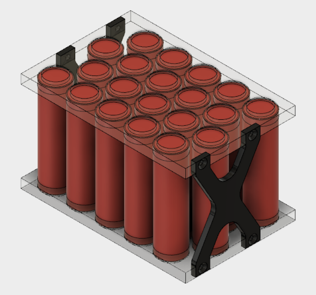
The calculations are kept simple, and ignored air resistance; I have calculated air resistance but it wasn't significant enough, especially during acceleration to warrant factoring it into the calculations. For my vehicle target weight, and wheel size, I decided I need to be able to supply a sustained 5kw.  To avoid needing an impractical amount of current, I aimed to keep the volts to amps ratio at 1:1. Because the micro controller I want to use has only 16 analog inputs, this means I can monitor at most 16 cells in series. Working this in to my target voltage/current ratio of 1:1, I settled on a battery topology of 16s20p. This gives a maximum power output 6.4kw at 5 Amps/cell, and a nominal power output of 2.9kw at 2.5 Amps/cell.

But enough of murky math, on to the design details. I decided I wanted a modular batter for several reasons. First was cost; I could start with fewer modulus and in case this whole thing didn't work out or I couldn't make it safe enough, I wouldn't be out a lot of cash in cells. If it did work, I could add more modulus later. Second was charging. Interfacing with a type 2 EV charger isn't particularly difficult, but it provides 240 volts, and the power supplies I would need to charge the battery would cost a lot, weigh a lot, and take up a lot of space. Charging on 120 volts wouldn't really make it any better as a high voltage and current would still be required.

The modular battery system allows modulus to be removed individually for charging. Its a novel idea and isn't practical for larger, or production vehicles. For a small moped, its a cool idea. I really like the physicality of removing modulus to charge them; it gives you a close connection to the bike. The BMS would signal to the rider what modulus need to be removed for charging. When a socket is not in use, it could be bridged with a jumper. The BMS could easily recognize the jumper and make appropriate adjustments.

The first sketches of the modular battery packs used a pivoting arrangement, with the loose end being held in by a rubber draw latch. This proved too complex for connectors between the pack and bike, as well as for waterproofing the modulus and the connections. The second idea was to use racks the modulus would slide into. The racks would be inside a waterproof enclosure with only 2 doors. This simplified connections and solved the waterproofing problem. This also made cooling much easier as forced air cooling in the battery box could now be used.

My first iteration of this design used mostly machine parts screwed together. I wanted all the module frames to be insulating and fire retardant if possible. End plates machine of polycarbonate spaced out by water jetted G10 spacers. This design was going to be expensive for fasteners, materials, and time. It also had stiffness issues, and would most likely suffer from cracking around the screws. After playing with it for a bit, I let it rest for a few months while I reevaluated.
First machined version of the rack mount modules
I don't remember where the idea came from, but I wanted to try the rack mount modules with 3D printed frames. I don't generally like hobby level 3D printing. Its probably from years of working with students who ask for help with poorly designed, printed parts trying to implement poorly thought out ideas. Note to the reader; drilling and tapping a 30% infilled part never works, no matter how many student groups try it. I wanted to try it anyway, what could go wrong. My first 3D printed design I stopped only halfway though; I really wasn't happy with it. I was still in the mindset of machining and weight saving; trying to make the parts and thin and light as possible.

First 3D printed version of rack mount modules 
You can probably see why I stopped. All the thin walls and tabs were too liable to snap off. It also would require a lot of support structure underneath due to a rim running around the underside. The model tree structure was also a mess and I had new ideas on how to structure it. I still didn't feel good about how I was designing it. Taking a pause, I thought about what I really was trying to do, not how I was going to do it. I started a new model with the goal of creating models as if these were going to be mass produced. What materials and techniques would be used then?

Some basic facts: it would be injection molded, it would most likely be out of glass filled nylon, it would most likely have torsional stiffness issues. These were the bases I needed. Attacking it again I got version 3.

Second 3D printed version of rack mount modules
I am very pleased with how version 3 came out, even though I already have improvements in my head. All the cells are parallel with each other, with spaces between for air flow. The contacts of the cells are soldered to copper bus bars under the front and rear covers. Both of these bus bars terminate in the tab on the front right of the module, where they attach to insulated copper pins that plug into sockets on the rack mounts. The tab is offset to allow two modules to oppose each other and use a central set of sockets.

Half the battery pack. Note how all the tabs nest together. 
All of these modules are connected in series
Layout of sockets on the rack mount
The connection pins are surrounded by a plastic tube to prevent accidental shorting. As these modulus are going to be removed regularly, its very important the modules are safe. The sockets on the rack mount have a unique shape. They allow for modules to be connected in series with appropriate polarity and allow the same packs to be used on either side of the sockets. I will most likely have a post in future with details and models of the sockets and rack mount. This central set of sockets would also have LEDs, one for each module to show the rider which modules have the lowest voltage and need to be charged next. The central sockets will also have spring contacts to connect to the module for temperature monitoring.

I at first planned to use RTDs of some kind, but this would require additional analog inputs on the micro controller. Thinking about how I would process these inputs, I realized all I would be doing is monitoring them in reference to a threshold value. I don't need a micro controllers for this, I can just use digital thermal switches wired to digital inputs. Only two contact are needed for multiple switches to be wired in parallel. If any run over temperature, the circuit will close causing a system shutdown.

The high current pins with their protection. The two small holes will receive press fit copper contact for thermal switches
 The front and rear frames are deeply ribbed to improve their area moment of inertial to reduce deformation. I also tried to make the connecting surfaces between the two frames as large as possible to increase stiffness. The two halves are held together with 6 screws specific for plastic. The square grooves on the outside edges are for the rack mounts. 6mm rails will be on the racks and the modules will slide into them. The filled in sections near the corners on the rear frame in the photo below is to allow for a place for the cover plate screws to attach. I also predict the corners will get abused a lot, so I made their walls thicker.

Rear frame. Note deeply ribbed and crossed base section
Front and rear frames assembeled
The copper bus bars are distinct to each side. To run power from the rear from to the front frame where the connectors are, a thin piece of copper runs up the bottom of a rail groove. This is fairly well sheltered so I am not worried about shorting. I also plan to cover this run with a thick piece of Kapton tape just to be safe. The batteries will be soldered to the copper bus bars with small jumper wires. The jumpers will be sized with a fusing current around 5-6 amps. This is a safety measure in case any cell is over current. The wire will melt and disconnect the cell. This is similar to how Tesla builds their batteries. The bus bars will just be held in place with some hot glue or CA glue. On the front frame the two bus bars get pretty close to one another. There is a least a 5mm air gap. I'm not worried about this because the bus bars wont move, and there is at most a 4 volt differential between these bus bars. There is very little chance of anything happening.

Upper bus bar showing the termination points in the lower right on the tab
Detail showing rear bus bar running up the bottom of a rack mount groove 
The front and back covers serve just to cover the bus bars and are held on with smaller versions of the designed for plastic screws. Fasteners will cost a lot for these modules. I already know how I'm going to eliminate 4 from the next design iteration, but I refuse to save money by buying phillips or slotted head screws. I won't do it. All in all the pack is very light, weighing in at 1.47kg, with only 80g of that being the plastic frames and copper bus bars.

Like I mentioned I already have ideas to make this design more reliable, use fewer screws, and have easier to assemble bus bars. I also need to incorporate a handle somewhere to allow easy removal from a slot in the rack. I also worry the tab holding the high current pins will break, but talking to manager of our maker space, he assured me there is little worry of it breaking. The next design will include the basic structure of the central sockets as well as the battery packs.

Saturday, April 28, 2018

Transverse Flux Motor V6

This is part of a larger project I started in some free time over the last summer. I was on co-op with a company working on a hybrid system. Being exposed to the industry made me realize that what i thought was the gradual and eventual transition it hybrid and electric vehicles isn't happening as fast as I thought. I always had an interest in electric vehicles because of their emissions potentials and because they are quiet. I decided to get back into electric vehicles. My school has a few electric vehicles and hybrid electric teams. I have tried attending meetings with all of them and talking with team leadership about team vision and plans. While I believe the teams are doing some really cool work, I find myself incompatible with the team cultures and operation models.

I instead decided to design my own electric vehicle. Cars are cool but I already have a car, so I don't really need a second one. Cars are also very challenging to build them road legal, let alone finding someone to insure you. For a while I rode a 1982 Honda moped and loved it. Eventually I sold it when I moved and I've really missed it. In my area, you don't need a motorcycle license for a moped and they are required to be inspected. They are also much easier to be insured. So I started sketching and brainstorming for a small electric moped.

I want to design everything myself; battery, BMS, motor, motor controller, frame. This post focuses on the motor design I settled on and the first version of the model I developed. I began by reading research papers. There is a lot on forums about motor design but much of it lacks solid engineering fact behind it; research papers provided the detailed information. Traditional laminated core in-runner motors I decided were too complex to build, even though they were the most common. They require a lot of reliance on outside vendors to cut the laminations, and a ton of time winding the slots. I wanted something simple and easy.

Reading research papers about various motor designs, I found something called a transverse flux motor. Originally an in-runner motor, I decided an out-runner with a Halbach array would give the highest torque density. After playing around with 6 different sizes and configurations, I finished a small scale model of the motor described. This motor only has two phases as that is all that is required. It is designed much like out-runner motors found in model aircraft.

Finished transverse flux motor

Finished transverse flux motor with rotor removed, only one phase is shown.
 Each phase has only one large coil. Interlaced around it are small horseshoe shaped laminations. They alternate inside and outside the coil, causing a reversed polarity on each horseshoe. The two phases are offset by halve a phase so no offset would be required in the magnets in the rotor. The light grey annulus is the mounting surface for the motor. The horseshoe laminations key into this mounting structure and and spaced apart by plastic insulators. The two phases are held in place by a lock nut on the back of the mounting structure.

Cross section of the phase, blue lines show where the copper winding would be
 The rotor is made of a single tube of plastic, slotted internally to space out the permanent magnets. Its a very unconventional design and difficult to prototype, but it is the best way I could think of doing it without laminating it. On the rear end is a cap with the main bearing in it. This bearing seats on to the stator via the phase lock nut. A small aluminum ring is pressed into the opposing side of the rotor to prevent possible collapse or deformation of the plastic tube. This design really needs a second bearing for support at one end or the other.

Motor rotor, note the complex fin shapes in the plastic tube and the single, large bearing


I ultimately rejected this design because of the complexity of the rotor, and the wiring of the leads out of the phase. With how I wanted to build it, large or small, there was virtually no space to run the power leads from the rear most phase to the mounting flange. I eventually decided to move to an axial flux motor design. There are many documented cases of axial flux motors performing to very high standards while there are virtually none of transverse flux motors preforming at high levels.

My designs for axial flux motors will be featured in future posts.
 

Thursday, April 26, 2018

A Sight Development

    One of my longest running distinct design projects is an Olympic recurve style sight for target archery. Finally coming to fruition after more than three years of design and sketches, this post will outline some of the features and design process I went through building this sight. For those who don't know what a recurve archery sigh is, it is a small aperture that is adjustable in vertical and horizontal axis and is supported a distance from the bow.
 
    I have been doing archery for nearly 10 years now and have been using my same equipment seven of them. This project spawned out of discontentment in my current sight. Being a capable engineer, I couldn't justify the price of a high quality production sight, so I toyed with the idea of building one. There were a few distinct features I wanted that could be found in commercially available products, as well as many of my own ideas that I hadn't seen implemented anywhere and I wanted to try.


The final design
    The final design has detented screws on both axis for easy adjustment. This is common on most high end sights, with the difference being my design uses a smaller and finer pitch screw for vertical adjustment to reduce weight. Most sights use a larger screw to handle the side loading from having a nut that contacts the screw from only one side. I incorporated a half nut backer to eliminate any side loading on the screw.

    The horizontal adjustment went through perhaps the most design revisions of any element on the sight. My original sketches were based on current designs and used ground guide pins and a lead screw for adjustment. I tried for a long time to find an arrangement of pins and screw that would be very compact and light weight. After sketching on and off for 2 years, I took a break. When I came back, I saw all my old designs as overbuilt and would be better suited to industrial machinery or machines tools; far more than is needed for a sight.

    My next idea was to use a parallel flexible for the axis. While simple, it proved to be too large for my self imposed size restrictions and never made it beyond sketches. I started looking closer at my current sight and decided I could use the simple (and hard to adjust) mechanism from my current sight and adapt it to have larger control features and not require any locking screws.

The simple adjustment mechanism. Note: a spring is not visible in the model.
    This design uses a nut with a fit similar to that of a nyloc nut, threaded directly on to aperture's thread. By using the thread on the aperture, the weight and size of the mechanism is greatly reduced. With the flat on the nut resting against the cover plate, it cant rotate but will slide freely. Coarse adjustments can then be made by rotating the end of the aperture in 180 degree increments. Fine adjustments are made with the large knob which is detented into the body of the sight, and threaded onto the aperture. The whole system is preloaded with an internal spring.

    One of my other requirements was for the sight to collapse flat for storage. Most sights achieve this by having the aperture removable. My original idea was to have the entire aperture fold flat to the main frame, eliminating the chance of dropping small parts in the grass when shooting outside. This mechanism proved to be too large in my various designs so I opted for a removable aperture. With the new horizontal adjustment, the aperture alone could no longer be removable. Instead I made the whole horizontal adjustment mechanism removable.

    The removable element is indexed with two perpendicular planes, restricting two transnational and three rotational axis of movement. The final transnational axis is indexed with a flat head thumb screw (not seen above). The thumb screw is captive so it wont get lost.

    The sight extension is made from two thin wall unidirectional carbon fiber tube. When you shoot archery outdoors, you loose arrows. When you are looking for your arrows, you find other lost arrows. As such I have a collection of old, often broken arrows I've found over the years. I like saving useful and expensive things and these tube qualify. I wanted to reuse some of these tubes for the extension because they are very light, stiff, straight, and consistent in diameter. I am convinced the 2 tubes will be strong enough to resist and bending moment, but I have reservations twisting them about their axis. If I build this sight and I find the extension is not torsionally rigid enough, I will add simple spacing braces between the two tubes at intervals down their length.

FEA of side loading of the extension with spreader brackets measuring for deflection


As you twist a 2 tube system like this, the midpoints of the tube tend to bend closer to each other. If you brace these apart, you are then transforming the torsional and bending forces on the individual tubes to tension forces, which tubes are much stiffer in. This would be a vary simple addition to make if needed.

Designing and modeling this project was a lot a fun and the culmination of more than 3 years of ideas and sketches, consulting with engineers, archery professionals and amateurs. I'm currently in the middle of building this sight with about 50% of components complete (by number). By amount of work, I would say its more like 70% complete. I worked from the most complex components - bed, saddle, carrier, split nut - first. If any of these components didn't work out as intended, I wouldn't have wasted time on a lot of the simpler components.


Tiger Bot VII Bipedal Robot

This is more of a stub post. Tiger Bot is one of the multiyear senior projects at my university. As I work for the senior design program at my, this was one of the projects I worked on and one of the most complex our shop has managed in the last few years. The task for the team was to design and build a bipedal robotics research platform that mimics human anatomy. This team was only to design the robot, not to program dynamic walk cycles. Below are photos of and models of some of the parts I made for this project. In total I did over 40 parts for this, most of them CAM. All programming was done in Fusion360. Because the number of CNC machined parts on this project was so high, I also worked with team members to teach them how to use the Fusion360 CAM package and run 2-axis CNC mills so they could produce some of the lower complexity parts.

Full documentation of the project can be found here.

Robot near final assembly, standing about 1.5 meters

External hip plates in aluminum, 2 made
Toe plates in aluminium, 8 made
Foot strain gauge structures in aluminum, 2 made
Arm servo replacement face plates, in aluminum, 2 made
Hip servo replacement face plates in aluminum, 2 made
Knee harmonic drive mounting bracket in aluminum, mirrored set made
Ankle servo replacement face plates in aluminum, 2 made
Heel plate in aluminum, mirrored set made

Sunday, April 22, 2018

Homemade Carbide Shank Boring Bar

    This project originated from a scrap find. In our carbide scrap at work, someone had blown up a long reach carbide end mill. Only the flutes were damaged and a considerable length of untouched carbide was left behind. Being a pack rat who found a large piece of his favorite material, the carbide shaft went into my tool box for a future project. At the time I didn't know what I was going to do with it.

Finished Boring Bar

   That was well over a year ago and not much happened with it. I had decided early on I wanted to make it into a carbide shank boring bar. The boring bar decision came out of a frustrating boring job on the lathe where I didn't have a good boring bar in the right size. Boring is one of my favorite operations but it can be finicky without a good bar. Work doesn't have and good boring bars. Carbide shank boring bars are the bees knees but are well outside my price range. Looking around online, many bars use odd or proprietary insert designs, or don't have a good selection of insert grades and geometries available. I do high mix work so the ability for one tool to preform well in a range of materials in critical. 

    With my first bar design ideas, I chose CCGT21.5 inserts because they are inexpensive and meet my generalist criteria. With some quick 3D models and a plastic prototype, I saw that it wasn't going to work. The clearance between bar and wall was too tight and insert pocket shape was less than ideal. I didn't save any of the models, prototypes or programs from that first design so I can't show it here.

    Shortly after this prototype, life got busy and I put away the project for a long time. Only recently, my schedule opened up and some A2 landed in my lap so I decided to give it a second shot. This time around I chose to use DCMT21.5, which are also available in a wide range of geometries, coatings and grades, and come with the added benefit that my workplace stocks them. Starting with the insert pocket and working out, I iterated through two versions to have a final design. I scrapped my first design after my modeling program broke down trying to handle blending all the curved surfaces I generated.

Model of boring bar head

    I did all design and programming in Fusion, mostly due to it being my CAM platform and an integrated CAE package is hard to pass up. Unlike my first attempt, the insert pocket walls on the final design have a 7 degree taper to match the insert walls. I had to make a decision on the joint between the steel head I was making and the carbide shank; notched or tapered. Some feature had to be made to increase the surface area for the joint. The notched joint has the benefit of simplicity, but leaves a translational axis of movement that needs to be monitored during assembly. The tapered joint restricts all axis of motion and is easier to form on the shank, but greatly complicates the machining of the head. 

    The biggest influence of the solution came from the bond type. Most bars use a brazed joint, with is preferred. I lack the experience and proper materials to effectively and cleanly braze carbide to steel and I wanted to finish this project. I decided to try something new and glue the head to the shank. Loctite 380 is well known for its high strength and impact resistance so I thought I would try it. The notched joint ends up having slightly more surface area than the tapered option I modeled. The notched also has the added benefit of a large part of the joint being subjected to high shear loading, which glue is strongest in. Some quick math suggested with my chosen geometry, the joint can support ~100kg of down force on the tip of the cutting tool. I don't expect to ever exceed. My only long term concerns with the glue joint is heat resistance. In a heavy cut with no coolant there is a chance the joint could become hot enough to fail.

Checking insert fit before cutting head off from stock

    If this happens I'll just glue it back together and keep using it. This whole bar was supposed to be a fun project so why not try something totally new. All the machining was programmed in Fusion and run on a Trak 2Op. The 2Op is an interesting machine. Its sold as a VMC that can be moved on a pallet jack and it has a great, compact work envelope. While intended for secondary and finishing operations, we use it at work for primary work because its rare we do more than 6 of the same part at a time. 1000mm is great in X if you are doing mold and die work, but when 95% of your parts fit in a 300mm cube, you don't need a huge machine. I love its compact size and the fact it has a tool changer for such a small machine. Despite this, the machine steel feels a bit 'hobby-ish'. Something more professional than a Tormach, but greatly lacking in some obvious areas. A 15k spindle, 25000mm/min axes, and a more powerful control and coolant pump and I would buy one. 

Operation 1 after roughing

    Tooling selection was pretty standard; an assortment of small, carbide endmills. My design did require a 7 degree/side tapered endmill. This wasn't explicitly necessary - I probably could have gotten good insert registration on square walls - but if its worth doing its worth overdoing. I ground a single lip tapered cutter on the surface grinder. The HSS blank used was an old tap from a job several years ago that I have been carrying around with my tools ever since; good to finally put it to use. A custom tool presented a problem for CAM programming; tool tip diameter. I took the tool on the optical compactor and measured both the angle of the cutting edge, and the diameter reduction from the shank. This allowed me to model the tool in Fusion and program the contours. I started out leaving material on the walls, and then slowly cut the walls back checking the insert fit relative to the locking screw hole until there was a perfect fit.

Custom ground cutter, HSS has the advantage that I can easily sharpen it

    After machining, it piece was shined up a bit with a sanding sponge and files to give a pretty snazzy looking part. The harder part was chopping the head off of the parent stock and adding the notch. Cutting off, easy on a band saw. To cut the notch I decided to set up on the surface grinder and plunge grind it. There is barely enough flat land next to the insert pocket and before the angled wall to clamp on, but I managed it. The ground notch was just centered by eye and checked against the carbide shank.  

    The vice in vice method of compound angles is by far my favorite. Its clean and easy. To set my 45 degree angle, I clamped this little 90-45-45 square I made to the jaw. For the grinding a dressed the side of the wheel square with the face of the wheel by clamping a diamond to the side of a block and traversing across the wheel.

Grinding set up

Homemade 45 degree square setting the angle

    This wrapped up all the machining operations and it was off to hardening. I brand all tools and projects I build for myself and this was no different. I hand engraved a small version of my logo above the insert pocket. I hardened the head with a MAPP gas torch. For such small parts, naturally aspirated torches have enough Watts to heat the part evenly. Naturally aspirated torches also have the advantage of producing a neutral flame. Oxy-acetylene torches - having oxygen forced into the flame - have the possibility to be oxidizing flames, that is you can supply too much oxygen for the stoichiometry of burning acetylene. This extra oxygen reacts readily with the hot metal and causes pitting and damage to the material surface. This doesn't happen so readily with naturally aspirated torches. 

Back side of the finished bar

    Oxides still formed on the surface of the head but they were very even and didn't damage the surface. I really quite like this matte grey finish the heat treat left, and it stayed through tempering. A quick clean up on the joint surface and some glue and the project was done. Eager to know if it worked, I bolted it up in a tool post and gave it a test cut. It preformed as best as I could have expected. 1 mm radial cut in aluminium at 7 x D overhand and not chatter. Light finishing passes caused chatter but I honestly attributed that more to a old, sloppy lathe and poor tool holding.

    I don't regret working on this. It was a lot of fun and I have a great tool at the end of it. It also gave me reason to exercise some of my little used tool grinding skills. Hopefully this tool will last for years to come.