I have been doing archery for nearly 10 years now and have been using my same equipment seven of them. This project spawned out of discontentment in my current sight. Being a capable engineer, I couldn't justify the price of a high quality production sight, so I toyed with the idea of building one. There were a few distinct features I wanted that could be found in commercially available products, as well as many of my own ideas that I hadn't seen implemented anywhere and I wanted to try.
 |
| The final design |
The horizontal adjustment went through perhaps the most design revisions of any element on the sight. My original sketches were based on current designs and used ground guide pins and a lead screw for adjustment. I tried for a long time to find an arrangement of pins and screw that would be very compact and light weight. After sketching on and off for 2 years, I took a break. When I came back, I saw all my old designs as overbuilt and would be better suited to industrial machinery or machines tools; far more than is needed for a sight.
My next idea was to use a parallel flexible for the axis. While simple, it proved to be too large for my self imposed size restrictions and never made it beyond sketches. I started looking closer at my current sight and decided I could use the simple (and hard to adjust) mechanism from my current sight and adapt it to have larger control features and not require any locking screws.
 |
| The simple adjustment mechanism. Note: a spring is not visible in the model. |
One of my other requirements was for the sight to collapse flat for storage. Most sights achieve this by having the aperture removable. My original idea was to have the entire aperture fold flat to the main frame, eliminating the chance of dropping small parts in the grass when shooting outside. This mechanism proved to be too large in my various designs so I opted for a removable aperture. With the new horizontal adjustment, the aperture alone could no longer be removable. Instead I made the whole horizontal adjustment mechanism removable.
The removable element is indexed with two perpendicular planes, restricting two transnational and three rotational axis of movement. The final transnational axis is indexed with a flat head thumb screw (not seen above). The thumb screw is captive so it wont get lost.
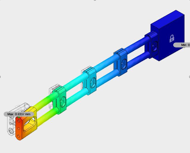
The sight extension is made from two thin wall unidirectional carbon fiber tube. When you shoot archery outdoors, you loose arrows. When you are looking for your arrows, you find other lost arrows. As such I have a collection of old, often broken arrows I've found over the years. I like saving useful and expensive things and these tube qualify. I wanted to reuse some of these tubes for the extension because they are very light, stiff, straight, and consistent in diameter. I am convinced the 2 tubes will be strong enough to resist and bending moment, but I have reservations twisting them about their axis. If I build this sight and I find the extension is not torsionally rigid enough, I will add simple spacing braces between the two tubes at intervals down their length.
 |
| FEA of side loading of the extension with spreader brackets measuring for deflection |
As you twist a 2 tube system like this, the midpoints of the tube tend to bend closer to each other. If you brace these apart, you are then transforming the torsional and bending forces on the individual tubes to tension forces, which tubes are much stiffer in. This would be a vary simple addition to make if needed.
Designing and modeling this project was a lot a fun and the culmination of more than 3 years of ideas and sketches, consulting with engineers, archery professionals and amateurs. I'm currently in the middle of building this sight with about 50% of components complete (by number). By amount of work, I would say its more like 70% complete. I worked from the most complex components - bed, saddle, carrier, split nut - first. If any of these components didn't work out as intended, I wouldn't have wasted time on a lot of the simpler components.
No comments:
Post a Comment