This is another post in the series about designing an electric moped. This post mainly details the system architecture and high level design. I avoid delving into the calculations I used. This post also doesn't cover BMS design and programming. This may be detailed in a future post.
For designing the battery I focused on the maximum power draw required. For my intended use - running around town while at school - I'm not particularly focused on range. While I aim for a 100km range, I don't have enough information about my preliminary designs to know if this is possible. I began by calculating maximum power required. The motor will draw maximum power when accelerating so I decided on required power from my desired acceleration.
The calculations are kept simple, and ignored air resistance; I have calculated air resistance but it wasn't significant enough, especially during acceleration to warrant factoring it into the calculations. For my vehicle target weight, and wheel size, I decided I need to be able to supply a sustained 5kw. To avoid needing an impractical amount of current, I aimed to keep the volts to amps ratio at 1:1. Because the micro controller I want to use has only 16 analog inputs, this means I can monitor at most 16 cells in series. Working this in to my target voltage/current ratio of 1:1, I settled on a battery topology of 16s20p. This gives a maximum power output 6.4kw at 5 Amps/cell, and a nominal power output of 2.9kw at 2.5 Amps/cell.
But enough of murky math, on to the design details. I decided I wanted a modular batter for several reasons. First was cost; I could start with fewer modulus and in case this whole thing didn't work out or I couldn't make it safe enough, I wouldn't be out a lot of cash in cells. If it did work, I could add more modulus later. Second was charging. Interfacing with a type 2 EV charger isn't particularly difficult, but it provides 240 volts, and the power supplies I would need to charge the battery would cost a lot, weigh a lot, and take up a lot of space. Charging on 120 volts wouldn't really make it any better as a high voltage and current would still be required.
The modular battery system allows modulus to be removed individually for charging. Its a novel idea and isn't practical for larger, or production vehicles. For a small moped, its a cool idea. I really like the physicality of removing modulus to charge them; it gives you a close connection to the bike. The BMS would signal to the rider what modulus need to be removed for charging. When a socket is not in use, it could be bridged with a jumper. The BMS could easily recognize the jumper and make appropriate adjustments.
The first sketches of the modular battery packs used a pivoting arrangement, with the loose end being held in by a rubber draw latch. This proved too complex for connectors between the pack and bike, as well as for waterproofing the modulus and the connections. The second idea was to use racks the modulus would slide into. The racks would be inside a waterproof enclosure with only 2 doors. This simplified connections and solved the waterproofing problem. This also made cooling much easier as forced air cooling in the battery box could now be used.
My first iteration of this design used mostly machine parts screwed together. I wanted all the module frames to be insulating and fire retardant if possible. End plates machine of polycarbonate spaced out by water jetted G10 spacers. This design was going to be expensive for fasteners, materials, and time. It also had stiffness issues, and would most likely suffer from cracking around the screws. After playing with it for a bit, I let it rest for a few months while I reevaluated.
 |
| First machined version of the rack mount modules |
I don't remember where the idea came from, but I wanted to try the rack mount modules with 3D printed frames. I don't generally like hobby level 3D printing. Its probably from years of working with students who ask for help with poorly designed, printed parts trying to implement poorly thought out ideas. Note to the reader; drilling and tapping a 30% infilled part never works, no matter how many student groups try it. I wanted to try it anyway, what could go wrong. My first 3D printed design I stopped only halfway though; I really wasn't happy with it. I was still in the mindset of machining and weight saving; trying to make the parts and thin and light as possible.
 |
| First 3D printed version of rack mount modules |
You can probably see why I stopped. All the thin walls and tabs were too liable to snap off. It also would require a lot of support structure underneath due to a rim running around the underside. The model tree structure was also a mess and I had new ideas on how to structure it. I still didn't feel good about how I was designing it. Taking a pause, I thought about what I really was trying to do, not how I was going to do it. I started a new model with the goal of creating models as if these were going to be mass produced. What materials and techniques would be used then?
Some basic facts: it would be injection molded, it would most likely be out of glass filled nylon, it would most likely have torsional stiffness issues. These were the bases I needed. Attacking it again I got version 3.
 |
| Second 3D printed version of rack mount modules |
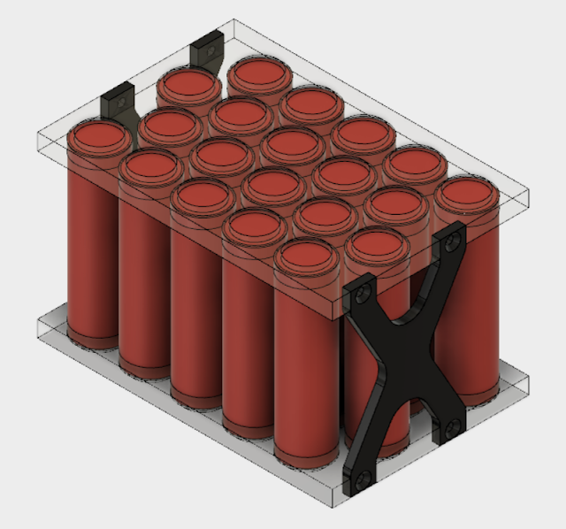
I am very pleased with how version 3 came out, even though I already have improvements in my head. All the cells are parallel with each other, with spaces between for air flow. The contacts of the cells are soldered to copper bus bars under the front and rear covers. Both of these bus bars terminate in the tab on the front right of the module, where they attach to insulated copper pins that plug into sockets on the rack mounts. The tab is offset to allow two modules to oppose each other and use a central set of sockets.
 |
| Half the battery pack. Note how all the tabs nest together. |
 |
| All of these modules are connected in series |
 |
| Layout of sockets on the rack mount |
The connection pins are surrounded by a plastic tube to prevent accidental shorting. As these modulus are going to be removed regularly, its very important the modules are safe. The sockets on the rack mount have a unique shape. They allow for modules to be connected in series with appropriate polarity and allow the same packs to be used on either side of the sockets. I will most likely have a post in future with details and models of the sockets and rack mount. This central set of sockets would also have LEDs, one for each module to show the rider which modules have the lowest voltage and need to be charged next. The central sockets will also have spring contacts to connect to the module for temperature monitoring.
I at first planned to use RTDs of some kind, but this would require additional analog inputs on the micro controller. Thinking about how I would process these inputs, I realized all I would be doing is monitoring them in reference to a threshold value. I don't need a micro controllers for this, I can just use digital thermal switches wired to digital inputs. Only two contact are needed for multiple switches to be wired in parallel. If any run over temperature, the circuit will close causing a system shutdown.
 |
| The high current pins with their protection. The two small holes will receive press fit copper contact for thermal switches |
The front and rear frames are deeply ribbed to improve their area moment of inertial to reduce deformation. I also tried to make the connecting surfaces between the two frames as large as possible to increase stiffness. The two halves are held together with 6 screws specific for plastic. The square grooves on the outside edges are for the rack mounts. 6mm rails will be on the racks and the modules will slide into them. The filled in sections near the corners on the rear frame in the photo below is to allow for a place for the cover plate screws to attach. I also predict the corners will get abused a lot, so I made their walls thicker.
 |
| Rear frame. Note deeply ribbed and crossed base section |
 |
| Front and rear frames assembeled |
The copper bus bars are distinct to each side. To run power from the rear from to the front frame where the connectors are, a thin piece of copper runs up the bottom of a rail groove. This is fairly well sheltered so I am not worried about shorting. I also plan to cover this run with a thick piece of Kapton tape just to be safe. The batteries will be soldered to the copper bus bars with small jumper wires. The jumpers will be sized with a fusing current around 5-6 amps. This is a safety measure in case any cell is over current. The wire will melt and disconnect the cell. This is similar to how Tesla builds their batteries. The bus bars will just be held in place with some hot glue or CA glue. On the front frame the two bus bars get pretty close to one another. There is a least a 5mm air gap. I'm not worried about this because the bus bars wont move, and there is at most a 4 volt differential between these bus bars. There is very little chance of anything happening.
 |
| Upper bus bar showing the termination points in the lower right on the tab |
 |
| Detail showing rear bus bar running up the bottom of a rack mount groove |
The front and back covers serve just to cover the bus bars and are held on with smaller versions of the designed for plastic screws. Fasteners will cost a lot for these modules. I already know how I'm going to eliminate 4 from the next design iteration, but I refuse to save money by buying phillips or slotted head screws. I won't do it. All in all the pack is very light, weighing in at 1.47kg, with only 80g of that being the plastic frames and copper bus bars.
Like I mentioned I already have ideas to make this design more reliable, use fewer screws, and have easier to assemble bus bars. I also need to incorporate a handle somewhere to allow easy removal from a slot in the rack. I also worry the tab holding the high current pins will break, but talking to manager of our maker space, he assured me there is little worry of it breaking. The next design will include the basic structure of the central sockets as well as the battery packs.


